Figure 1: General workflow for automated modelling of volumetric cracks geometry for BIM.
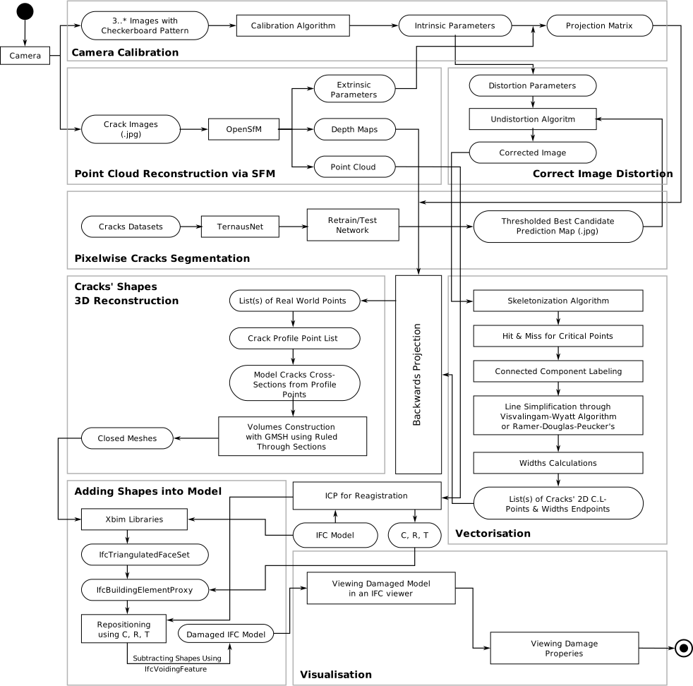
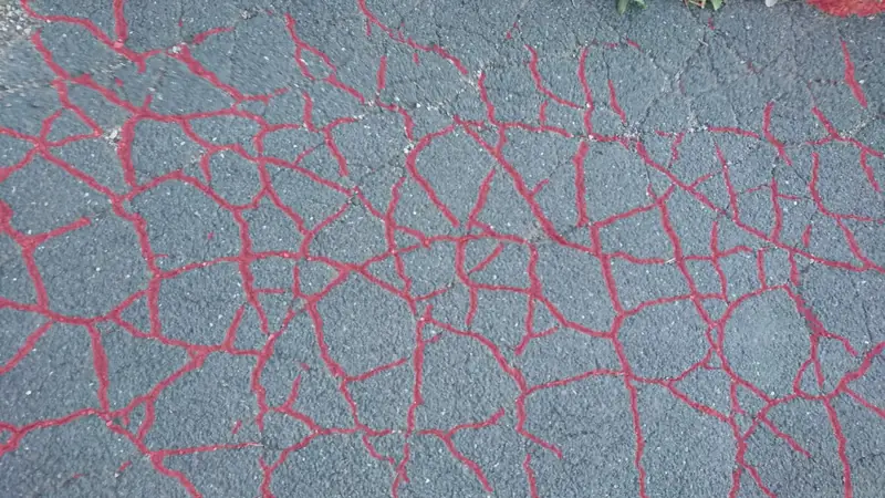
In this project, a comprehensive pipeline to reliably model solid shapes for cracking patterns automatically based on images was developed through a workflow comprising eight major steps starting from camera calibration, image distortion correction, point cloud reconstruction via Structure from Motion (SfM), pixelwise semantic segmentation of cracks using retrained deep learning model, vectorisation of cracks segmentation masks into pixel graphs and polylines, backprojection of 2D cracks into 3D and their shapes reconstruction, and 3D cracks embedding in, to last but not least BIM semantic enrichment and visualisation.
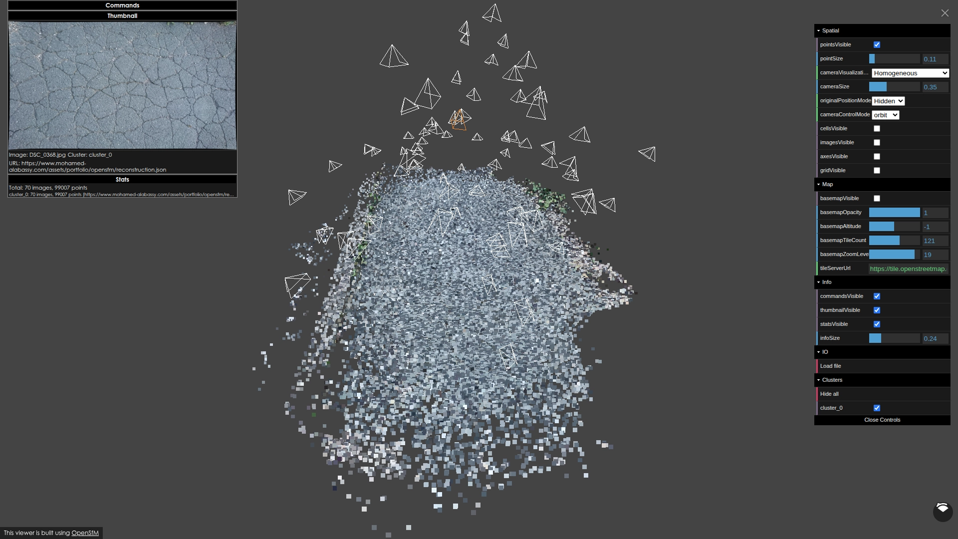
Classical methods for camera calibration were effective and utilised once per camera configuration. The 3D reconstruction of the point cloud based on the taken images of the case study not only provided the missing depth and scale information for each image, but also simplified extracting the position of the main points of particular interest for the cracks centre-polylines, speeding up the processing time and computation to model the crack shapes independent of any automated masking through segmentation of all underlying images or the reconstructed point cloud as a prerequisite.
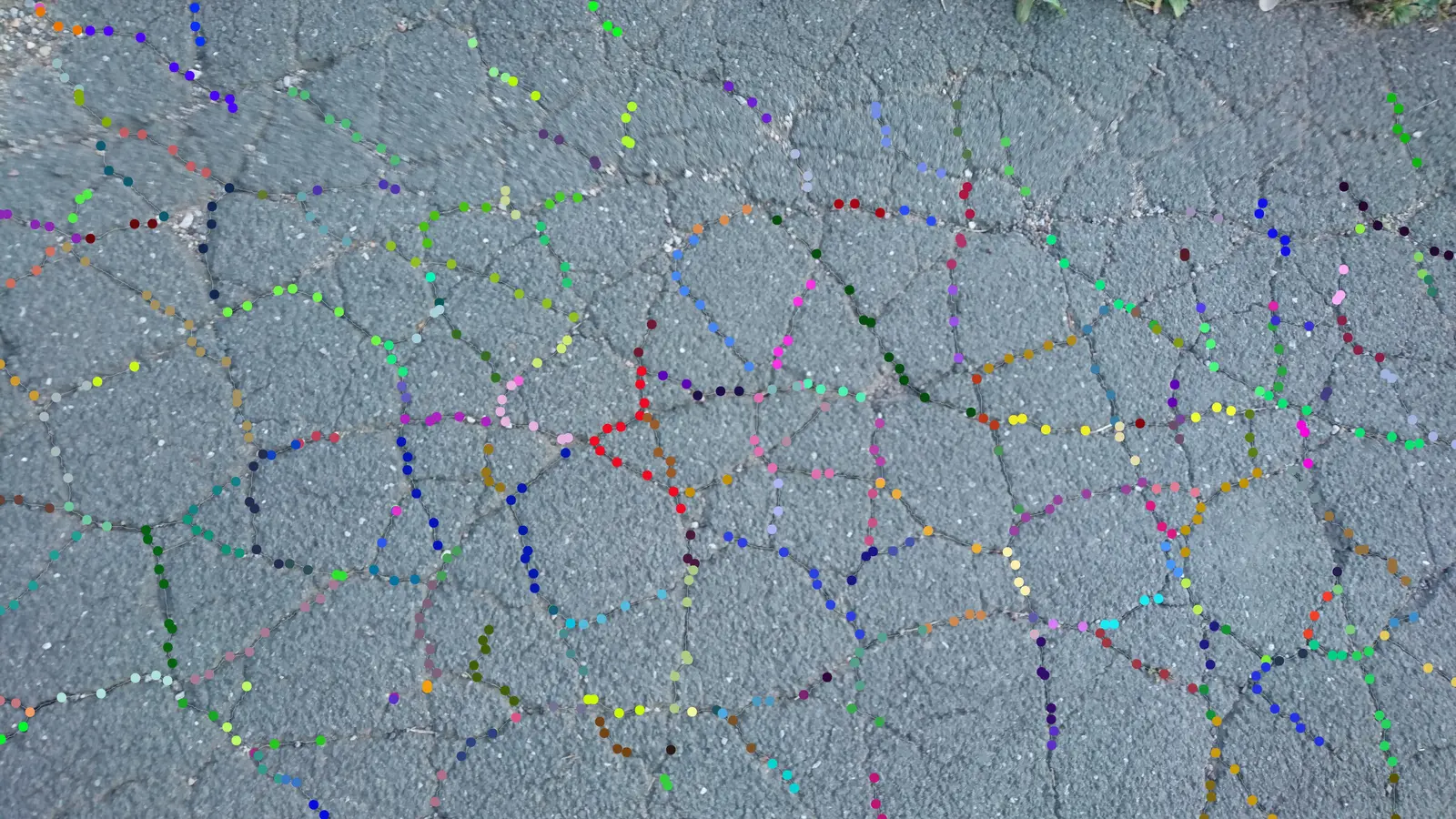
The OpenSfM library was found at the time of publishing in 2020 to be very robust, with its available functionalities well suited for the objective of post 3D reconstruction backwards projection. A retrained Deep Learning TernausNet with a VGG16 encoder architecture allowed for a reliable inferred semantic segmentation (i.e., classification of crack pixels) with good accuracy and IoU metrics achieved at evaluation. The retrained model performed robustly at deployment on the unseen case study images, which facilitated the application of several classical image analysis algorithms including, skeletonisation, morphological operations, edge detection, connected components labelling, line simplification and the euclidean distance transform to extract the main points comprising the centre-polylines of each segment and construct a pixel/voxel graph through skeletal analysis for the interconnected networks of cracking patterns, both in 2D and 3D.
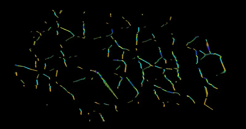
With the knowledge of those points of interest and all parameters of the perspective projection model the 2D pixels could be back-projected to the 3D scene through a single image and its prediction mask, and used to model the crack shapes after transforming their coordinates to align with the parent building element domain via through-sections extrusion. Such crack shapes could be then converted into various formats, depending on the use required, whether be it only for visualisation in IFC format, or performing more advanced FEM based structural analysis procedures, as they preclude the nodes for tetrahedrons, wires defining all trimmed surfaces, as well as the standard vertices, edges, and faces of a triangulated mesh.
Both the quality metrics of the modelled shapes provided in GMSH and the proper creation of voids in Blender demonstrate the validity of voided shapes and the visualisation limitations in IFC viewers therefore related to the geometry kernels inability to properly model complicated IFC products. The use of IfcOpenShell allowed for embedding the crack shapes into the IFC model as voiding features. Further details can be found in the relevant publications listed below.
Source Code & Supplementary Materials
- 1 - Github Repository: Pipeline Source Code
- 2 - OneDrive: Supplementary Thesis Materials
- 3 - GDrive: Supplementary Data
Publications
- Automated Approach for Building Information Modelling of Crack Damages via Image Segmentation and Image-based 3D Reconstruction
Alabassy, Mohamed Said Helmy (2021). In: 32nd Forum Bauinformatik (p. 123-130). Date: 09.09. - 10.09.2021. Darmstadt, Germany. DOI: 10.26083/tuprints-00021521. - Automated Approach for Building Information Modelling of Crack Damages via Image Segmentation and Image-based 3D Reconstruction
Alabassy, Mohamed Said Helmy (2021). Master's thesis. Bauhaus-Universität Weimar, Weimar, Germany. DOI: 10.25643/bauhaus-universitaet.6416.

1 - Camera CalibrationIntrinsic Camera Matrix
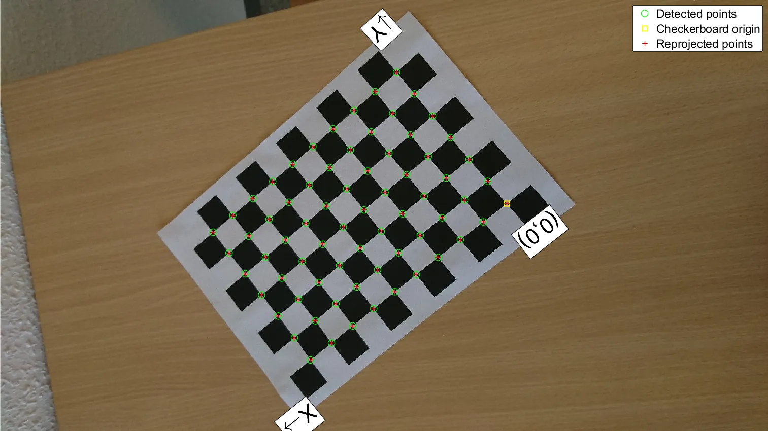

2 - Correct DistortionRectified Images
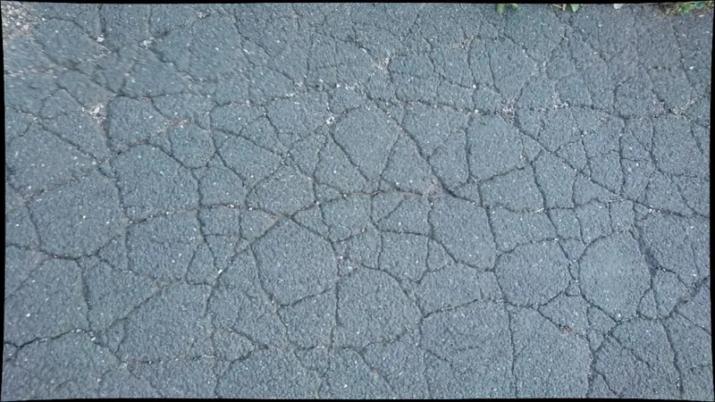

3 - Point Cloud ReconstructionOpenSfM Merged Dense PCD
4 - Pixelwise SegmentationDL Binary Segmentation Masks
5 - Vectorisation & GraphsCracks Pixel/Voxel Graphs
6 - Cracks' Shapes 3D ReconstructionBackwards Projection & Extrusion
7 - Adding Shapes into ModelSemantically Enriched BIM
8 - Visualisation & IFCFinal IFC File